
The Arduino micro-controller's are very popular, however sometimes they are just not powerful enough.
A lot of home-brewing ham's tend to switch to a Raspberry-Pi in this case, however often this isn't just the elegant solution they look for.
A Raspberry Pi compared to e.g. an Arduino Nano is large, expensive, boots way to slow, consumes a lot, needs a flash-drive ...
A better solution in this case is a more powerful micro-controller like the STM-32 "blue pil"
Where the Arduino Nano is 8-bit's, the STM-32 is a 32-bit's microcontroller, has more GPIO but isn't to much bigger than a Nano.
You can find them at a cheap price here:
https://www.banggood.com/STM32F103C8T6-Small-System-Board-Microcontrolle...
Even nicer is that you can program them using the Arduino-IDE and the Arduino sketch programming code !!
Yet to get there some steps are needed:
1. Install the necessary compiler components
______________________________________________________________________________________________________________________________
The STM32 is based on an ARM M0+ core also used in the "Arduino Zero" a 32bit version of the "Arduino UNO"
So installing the libraries for this board also installs all the components needed to work with the STM32
To do this in the Arduino-IDE go to "tools" next select "board" and all the way at the top of the list you'll find "board manager"
Select this and search for the library called "Arduino SAMD Boards (32-bits ARM Cortex-M0+)" that lists the "Arduino Zero" among the supported boards"
If you hover over this item you'll see an install button appear on the right-hand side. Click this "Install" button.
2. add the external STM Library
______________________________________________________________________________________________________________________________
Next we need to add a library that is non standard in the Arduino-IDE.
To do this go to the "file" tab and select "preferences"
On this page you'll find an item called "Additional Boards Manager URLs"
In this text-field paste the following URL:
http://dan.drown.org/stm32duino/package_STM32duino_index.json
In the lower right corner click "OK" to confirm.
3. install the external STM32 Library
______________________________________________________________________________________________________________________________
Go back to the same place where you installed the Arduino Zero SAMD library: "
"tools" next "board" and at the top of the list select "board manager"
As soon as you select "board manager" you'll see that automatically a library is downloaded.
If you scroll down now you'll see that an extra item appears at the bottom of the list called "STM32F1xx/GD32F1xx boards"
Install this library with the 'install" button on the right hand side
4. Select the correct board in the Arduino-IDE
______________________________________________________________________________________________________________________________
Now we need to select the correct hardware board in the IDE.
To do so go to "Tools" next "Board" scroll down the list and select "Generic STM32F103C series"
Normally this should be enough but in the case you have a 128k version you also need to select this by clicking "Variant" and next "20k RAM, 128k Flash"
5. Test the installation
______________________________________________________________________________________________________________________________
As far as software goes we're done. To test if everything is set up properly go to the Arduino-IDE and try to compile - but not upload! - a standard empty sketch (the sketch you get when you start the IDE normally). So press only the "V" compile button.
This should normally work fine.
If you would get the error that "arm-none-eabi-g++" is missing than most likely the installation of the "Arduino SAMD Boards (32-bits ARM Cortex-M0+)" library did not go well, so uninstall this library and try to install it again.
6. Connecting the Hardware CAUTION !!
______________________________________________________________________________________________________________________________
Now this is a tricky part. The STM32 has a USB connector but by default you can't program the micro-controller this way...
We can give it power and use it this way once it is programmed, but to upload code to this micro-controller you need to do so using the serial interface of the micro-controller. We'll thus need an extra cable from our PC and a USB to RS232 serial interface.
CAUTION!
Now pay attention here as unlike the Arduino NANO the STM32 runs on 3.3 Volts !!
So you can't just simply connect the serial pin's of the STM32 to your USB to RS232 serial interface.
You will need a 5V to 3.3V level-shifter for this. If you don't have one of these laying arround, you buy these really cheap on the internet just make sure it is a "bi-direction" version you can use with serial connections e.g. like this one:
https://www.banggood.com/Logic-Level-Converter-Bi-Directional-IIC-4-Way-...
Alternatively you can use a USB-RS232 convertor that has a 3.3V/5V voltage switch on it like this one:
https://www.banggood.com/USB-to-TTL-Serial-Port-Module-CH340-Adapter-Sup...
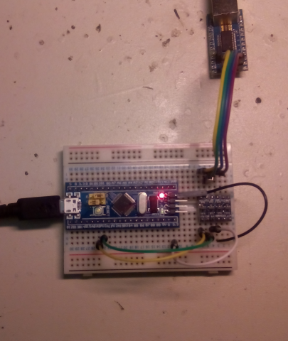
If you're using the level shifter than the wiring goes like this: (see also the image of this article)
- Connect the TX of the USB to RS232 convertor to the HV1 of the level shifter
- Connect the RX of the USB to RS232 convertor to the HV2 of the level shifter
- Connect the GND of the USB to RS232 convertor to the GND of the level shifter
- Connect the +5V (or Vcc) of the USB to RS232 convertor to the HV of the level shifter
Now the second part:
- Connect pin A9 on the STM32 to the LV1 of the levelshifter
- Connect pin A10 on the STM32 to the LV2 of the levelshifter
- Connect the GND of the STM32 to the GND of the levelshifter
- Connect the 3.3V of the STM32 to the LV of the levelshifter
And now where ready with the hardware and we can connect both USB cables to our PC, one on the micro-usb of the STM32 and the second-one going to our USB to RS232 convertor.
7. Place the STM32 in programming mode
______________________________________________________________________________________________________________________________
Unlike the Arduino's you need to change from programming to running mode on the STM32 by setting a hardware jumper.
So in order to program this device with the micro-usb connector on PCB-board facing left set the top-jumper of the two jumper's on the board to the right position.
8. Uploading
______________________________________________________________________________________________________________________________
Now everything is ready to upload. But if you would simply press upload on the Arduino-IDE now you would get an error.
This is because there is no automatic reset-puls going to the STM32 because of the serial interface.
So to upload code to the board press the little reset button on the STM32 and as soon as you release it quickly press the upload button on the Arduino-IDE.
This should now work without any errors.
9. Try the "Blink" sketch
______________________________________________________________________________________________________________________________
So all we have now is no errors but no action. To see at least a bit action on the board select the "Blink" sketch from the examples in the Arduino-IDE ( "file" and next "examples" then "1. Basics" and there you'll find "blink" )
To make it work on the STM32 in the code change "LED_BUILTIN" by "PC13" everywhere you see this.
Press reset, upload and there's the blinky !